
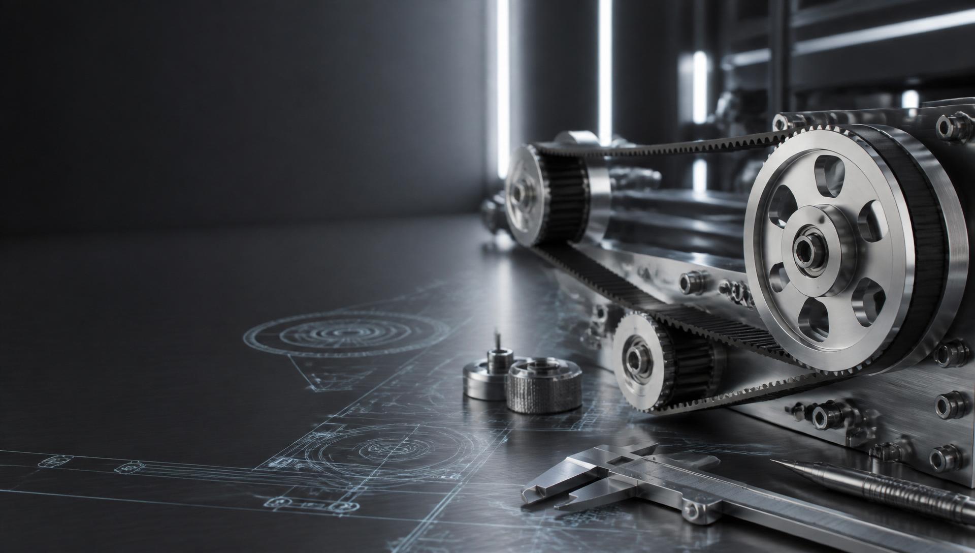
Timing Pulley Specifications
Materials, tooth profiles, bore configurations, flange options and surface finishes for MACHINING Force synchronous timing pulleys.
CNC-machined for synchronous drives
Every timing pulley ships to a documented profile, material, bore and flange specification. Custom tooth counts, colored anodizing and clamping-hub bores are quoted to your drawing.
Material
Aluminum 6061-T6 (anodized natural, black or blue), C45 steel, 40Cr alloy, 304 stainless
6061-T6 aluminum is the default for low-inertia, high-speed positioning drives; steel is used where wear resistance or maximum torque governs; stainless for washdown and marine environments.
Tooth profiles
HTD 3M/5M/8M/14M · Metric T 2.5/5/10/20 · Inch MXL/XL/L/H/XH · GT/GT2 2MR/3MR/5MR
All tooth profiles are CNC-machined to ISO 5294 or the relevant belt manufacturer standard, ensuring perfect belt-pulley engagement over the full service life of the drive.
Tooth count
10 to 192 teeth depending on pitch and diameter
Minimum tooth counts vary by profile — 12 teeth for HTD 3M, 22 teeth for HTD 14M — to preserve belt bending life at the pulley wrap.
Bore configuration
Pilot bore, finished bore with keyway, taper lock bushing, or clamping hub
Clamping hubs deliver zero-backlash concentric connection without keyways — the preferred specification for precision indexing, servo and robotic drives.
Flange options
Single flange, double flange, or no flange (flangeless for wide belts)
Flanges retain the belt against side thrust and misalignment; on two-pulley drives one pulley is typically double-flanged and the other flangeless to allow belt tracking.
Surface finish
Clear anodized (standard), black anodized, blue anodized, hard anodized, zinc plated, black oxide
Hard anodizing adds a 25-50 µm ceramic-like layer that resists abrasion from dust and debris in industrial environments — recommended above 3,000 rpm.
Balancing
Static balance standard; dynamic balance for pulleys above 3,000 RPM
Dynamic balance to ISO 1940 G6.3 is applied to reduce vibration in high-speed spindle, supercharger and blower drives.
Max bore diameter
Typically 30% to 60% of outside diameter
Wall thickness between the bore and the tooth root is engineered to preserve tooth stiffness under load — oversized bores are quoted case-by-case.
Ready to work with Force Machining?
Send drawings, specs or a rough idea — our engineers get back within one business day.