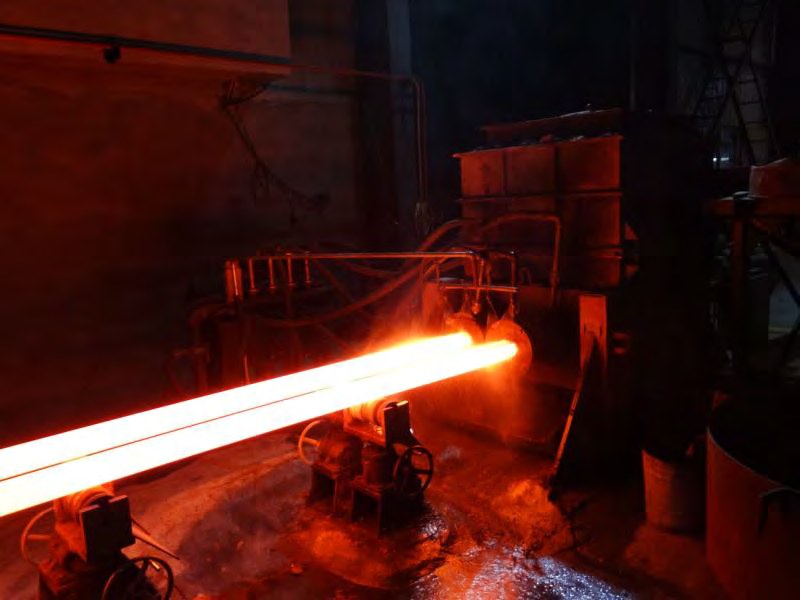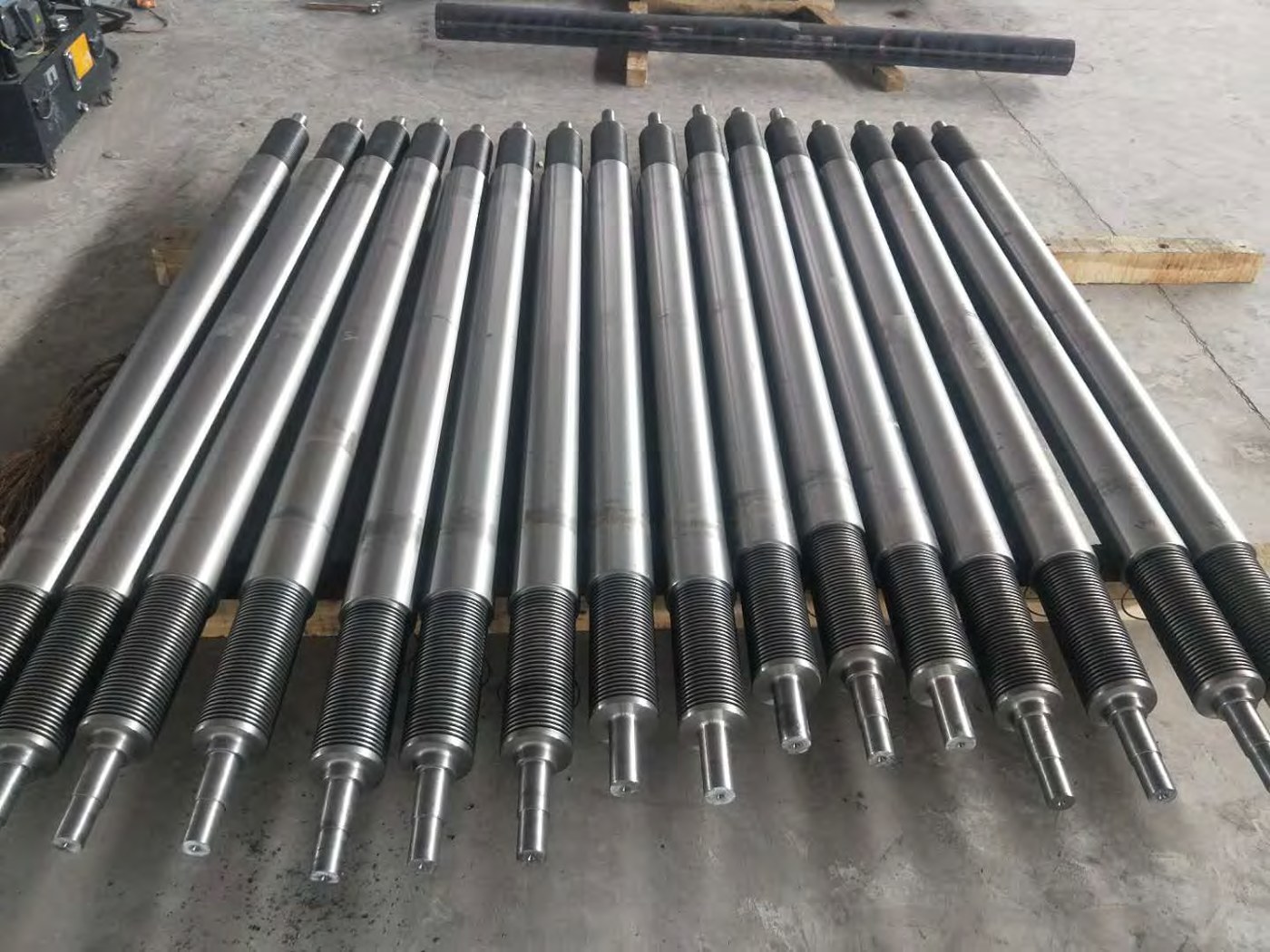
Continuous cast bar looks simple in the yard: a straight length of iron. Producing it to a stable, certifiable specification depends on holding several process variables inside narrow windows at the same time — chemistry, temperature, cooling rate and withdrawal cycle.
This is how the line runs, stage by stage, and what is measured at each point.
Stage 1 — Charge make-up and melting
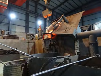
The charge combines pig iron, selected steel scrap, returns and carburiser, calculated to hit the target carbon and silicon for the grade. Melting is in an induction furnace, which gives close temperature control and no fuel-borne sulphur pick-up.
A pre-treatment spectrometer sample confirms carbon, silicon, manganese, phosphorus and sulphur before anything moves. Ductile grades demand sulphur down at 0.011–0.012% because residual sulphur consumes the magnesium needed for nodularisation.
Stage 2 — Nodularisation and inoculation
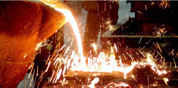
For ductile grades the melt is magnesium-treated in the ladle, then inoculated with a ferrosilicon-based inoculant to seed graphite nucleation sites. Both treatments fade with time and temperature, so the transfer window to the holding furnace is controlled tightly. Target spheroidisation is approximately 90% with nodule grading 1–2.
Gray grades skip nodularisation but are still inoculated to control chill and stabilise flake distribution.
Stage 3 — Holding furnace and graphite die
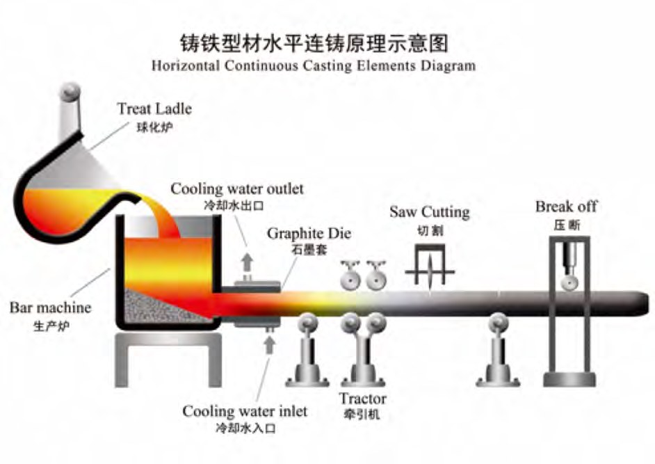
Treated iron enters the bar machine, a heated holding furnace that maintains pouring temperature and a constant metallostatic head at the die. That constant head is what feeds solidification shrinkage continuously and keeps the bar free of internal cavities.
The graphite die is surrounded by a water jacket with monitored inlet and outlet temperatures. Cooling rate sets the depth of the solidified shell and therefore the graphite morphology and matrix.
Stage 4 — Controlled withdrawal
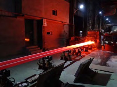
A servo tractor pulls the bar in a programmed pull–dwell cycle rather than continuously. The dwell lets the shell thicken and re-weld to the growing front; the pull advances the bar by a set increment. Pull length, dwell time and water flow are tuned per grade and per section size, and are the primary levers over structure and surface quality.
Stage 5 — Cut-off, straightening and finishing
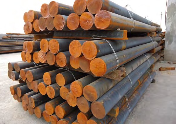
Bar is saw-cut or break-off cut to stock length, checked for bow against the tolerance table (≤2.0–6.0 mm/m depending on section and grade), heat-number marked, bundled and moved to the yard.

Stage 6 — Inspection and certification
- Spectrometric analysis on every heat — C, Si, Mn, P, S plus residual Cr and Ni.
- Tensile, yield and elongation testing on samples taken at 1/4 diameter (round) or 1/4 diagonal (square and rectangle).
- Brinell hardness verification against the grade band.
- Metallographic examination for spheroidisation rate, nodule grading and matrix structure.
- Dimensional and bow inspection against the as-cast tolerance table.
- Mill certificate issued per heat; EN 10204 3.1 certification available on request.
| Shape | Size (mm) | Tolerance — gray iron | Tolerance — ductile iron | Max. bow (mm/m) gray / ductile | Machining allowance (mm) gray / ductile |
|---|---|---|---|---|---|
| Round | Φ20 – Φ45 | 0 / +1.0 | 0 / +2.0 | ≤5.0 / ≤6.0 | 0.5 / 0.8 |
| Round | Φ45 – Φ65 | 0 / +1.5 | 0 / +2.0 | ≤3.0 / ≤4.0 | 1.5 / 1.5 |
| Round | Φ65 – Φ100 | 0 / +2.0 | 0 / +2.5 | ≤2.0 / ≤2.5 | 2.0 / 2.0 |
| Round | Φ100 – Φ200 | 0 / +3.0 | 0 / +4.0 | ≤2.0 / ≤2.5 | 0.5 / 3.5 |
| Round | Φ200 – Φ280 | −1.0 / +5.0 | −1.0 / +6.0 | ≤2.0 / ≤2.5 | 1.5 / 6.0 |
| Round | Φ280 – Φ500 | −1.0 / +8.0 | −2.0 / +10.0 | ≤2.0 / ≤2.5 | 2.0 / 8.0 |
| Square | Thickness 25 – 50 | 0 / +1.0 | 0 / +2.5 | ≤5.0 / ≤5.5 | 2.0 / 2.0 |
| Square | Thickness 50 – 100 | 0 / +1.5 | 0 / +3.0 | ≤4.0 / ≤4.5 | 3.0 / 3.0 |
| Square | Thickness 100 – 200 | 0 / +5.0 | 0 / +8.0 | ≤3.0 / ≤3.5 | 2.0 / 4.5 |
| Square | Thickness 200 – 320 | −1.0 / +8.0 | 0 / +10.0 | ≤3.0 / ≤3.5 | 3.0 / 6.0 |
| Semicircle | Height 40 – 85 | 0 / +1.5 | 0 / +2.0 | ≤4.0 / ≤4.5 | 2.0 / 2.5 |
| Semicircle | Height 85 – 180 | 0 / +2.5 | 0 / +3.0 | ≤3.0 / ≤3.5 | 3.0 / 4.0 |
As-cast dimensional tolerance and machining allowance, Force Machining continuous cast bar
- A constant metallostatic head behind the die is the single most important variable for internal soundness.
- Ductile grades need sulphur at 0.011–0.012% before magnesium treatment can nodularise the graphite effectively.
- Pull length, dwell time and cooling water flow control the graphite structure and surface quality.
- Test specimens are taken at 1/4 diameter or 1/4 diagonal, matching international practice.
- Every heat is certified for chemistry and mechanical properties; EN 10204 3.1 is available.