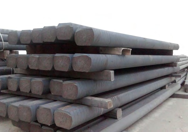
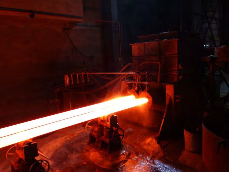
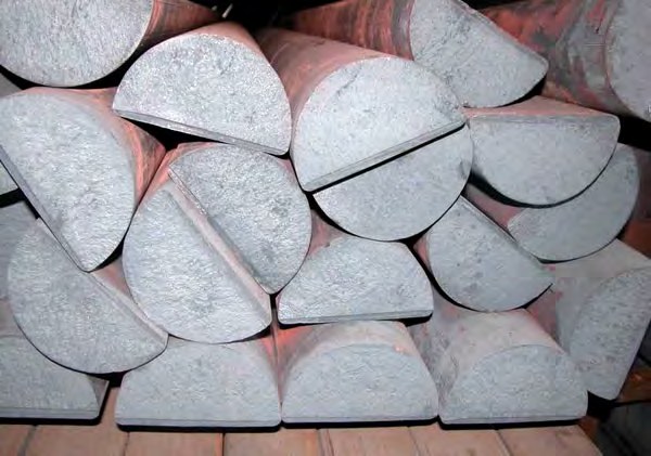
Continuous cast iron bar is semi-finished cast iron produced as a continuous length of solid section — round, square, rectangular or semicircular — rather than as an individually moulded casting. Molten iron is held in a heated furnace, drawn horizontally through a water-cooled graphite die, solidified under controlled thermal conditions and then cut to length.
The result is a bar with a dense, uniform, fine-grained structure and no sand inclusions, gas porosity or feeder-related shrinkage cavities. For machine shops it behaves like a free-machining bar stock: you cut it from solid, and what comes off the machine is a finished component.
This article explains the process, the metallurgy it produces, the grades and sizes available from Force Machining, and how to decide whether bar stock or a discrete casting is the right route for your part.
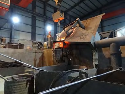
How horizontal continuous casting works
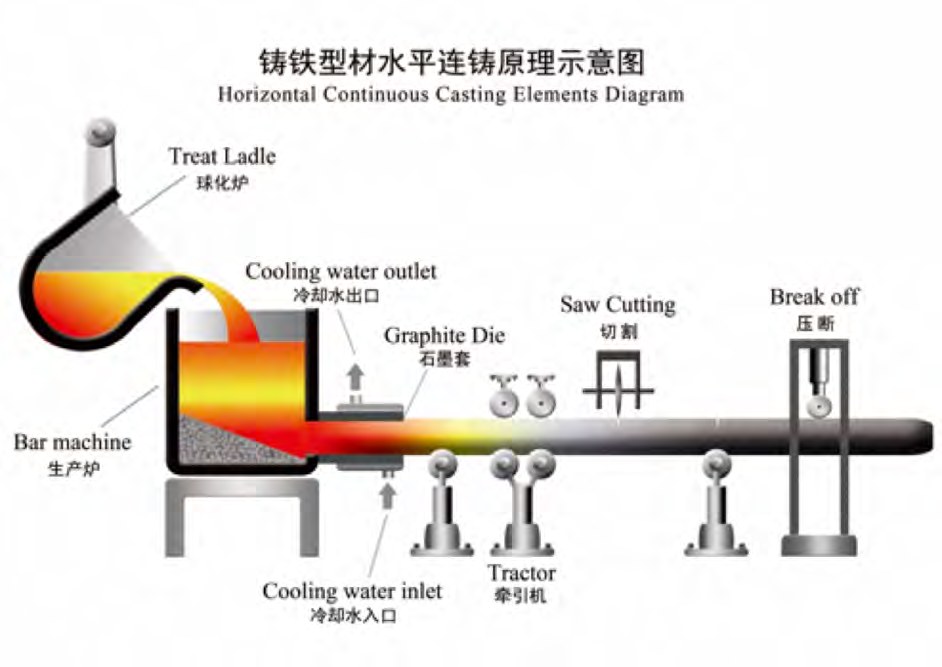
The process runs in five controlled stages:
- Melting and treatment — base iron is melted, desulphurised and, for ductile grades, treated with magnesium in the treat ladle to nodularise the graphite.
- Holding furnace — treated iron is transferred to the bar machine, which keeps the metal at a stable pouring temperature and feeds the die under a constant metallostatic head.
- Graphite die — the die is jacketed with circulating cooling water. Iron solidifies from the die wall inward, forming a solid skin that grows as the bar advances.
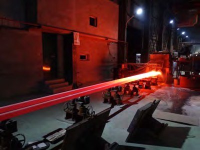
- Withdrawal tractor — a servo-driven tractor pulls the bar in a controlled stop-and-go cycle. Withdrawal rate, dwell time and water flow together set the solidification front and therefore the graphite structure.
- Cut-off — the bar is saw-cut or break-off cut to stock length, marked and moved to the yard.
Because the metal solidifies against a graphite wall under directional cooling and constant feed pressure, the shrinkage that normally forms cavities in a sand mould is continuously fed by liquid metal behind it. That single mechanism is the reason continuous cast bar is metallurgically sound through the section.
What the process does to the metallurgy
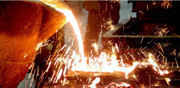
Rapid, directional solidification against the graphite die produces a fine, evenly distributed graphite phase and a tight pearlite or ferrite matrix. In ductile grades this shows up as a high nodule count with a spheroidisation rate around 90% and nodule grading 1–2, compared with 50–65% and grading 4–6 typical of the same nominal grade poured into sand.
Chemistry is also cleaner, because the melt is treated and held rather than poured through a running system. Phosphorus is held at ≤0.036% and sulphur at 0.011–0.012%, both of which directly improve toughness and tool life.
Dense structure and low residuals mean pressure tightness without impregnation, predictable hardness for consistent tooling, and no surprise sand hole discovered after 40 minutes of machining.
Grades produced as continuous cast bar
Force Machining produces three gray iron grades and four ductile iron grades as standard, all cross-referenced to the international designations your drawing is most likely to call out.
| China (GB) | U.S.A. (ASTM) | E.U. (EN) | Germany (DIN) | Japan (JIS) |
|---|---|---|---|---|
| HT200 | No. 30 | EN-GJL-200 | GG20 | FC200 |
| HT250 | No. 35 | EN-GJL-250 | GG25 | FC250 |
| HT300 | No. 45 | EN-GJL-300 | GG30 | FC300 |
| QT400-18 | 60-40-18 | EN-GJS-400-18 | GGG40 | FCD400 |
| QT450-10 | 65-45-12 | EN-GJS-450-10 | GGG45 | FCD450 |
| QT500-7 | 70-50-05 | EN-GJS-500-7 | GGG50 | FCD500 |
| QT600-3 | 80-55-06 | EN-GJS-600-3 | GGG60 | FCD600 |
Core continuous cast grades and international equivalents
Gray grades (HT200–HT300 / GG20–GG30 / FC200–FC300) carry flake graphite and are chosen for damping, thermal conductivity and sliding wear. Ductile grades (QT400-18 to QT600-3 / GGG40–GGG60 / FCD400–FCD600) carry nodular graphite and are chosen where strength, elongation and impact matter.
Standard profiles, sizes and tolerances
| Profile | Size range |
|---|---|
| Round | Φ18 – Φ600 mm |
| Square | 30×30 – 425×425 mm |
| Rectangle | 30×40 – 360×470 mm |
| Semicircle | R30 – R180 mm |
Available profiles and size envelope

As-cast bar is supplied with a machining allowance so the finished part is cut entirely from sound metal:
| Shape | Size (mm) | Tolerance — gray iron | Tolerance — ductile iron | Max. bow (mm/m) gray / ductile | Machining allowance (mm) gray / ductile |
|---|---|---|---|---|---|
| Round | Φ20 – Φ45 | 0 / +1.0 | 0 / +2.0 | ≤5.0 / ≤6.0 | 0.5 / 0.8 |
| Round | Φ45 – Φ65 | 0 / +1.5 | 0 / +2.0 | ≤3.0 / ≤4.0 | 1.5 / 1.5 |
| Round | Φ65 – Φ100 | 0 / +2.0 | 0 / +2.5 | ≤2.0 / ≤2.5 | 2.0 / 2.0 |
| Round | Φ100 – Φ200 | 0 / +3.0 | 0 / +4.0 | ≤2.0 / ≤2.5 | 0.5 / 3.5 |
| Round | Φ200 – Φ280 | −1.0 / +5.0 | −1.0 / +6.0 | ≤2.0 / ≤2.5 | 1.5 / 6.0 |
| Round | Φ280 – Φ500 | −1.0 / +8.0 | −2.0 / +10.0 | ≤2.0 / ≤2.5 | 2.0 / 8.0 |
| Square | Thickness 25 – 50 | 0 / +1.0 | 0 / +2.5 | ≤5.0 / ≤5.5 | 2.0 / 2.0 |
| Square | Thickness 50 – 100 | 0 / +1.5 | 0 / +3.0 | ≤4.0 / ≤4.5 | 3.0 / 3.0 |
| Square | Thickness 100 – 200 | 0 / +5.0 | 0 / +8.0 | ≤3.0 / ≤3.5 | 2.0 / 4.5 |
| Square | Thickness 200 – 320 | −1.0 / +8.0 | 0 / +10.0 | ≤3.0 / ≤3.5 | 3.0 / 6.0 |
| Semicircle | Height 40 – 85 | 0 / +1.5 | 0 / +2.0 | ≤4.0 / ≤4.5 | 2.0 / 2.5 |
| Semicircle | Height 85 – 180 | 0 / +2.5 | 0 / +3.0 | ≤3.0 / ≤3.5 | 3.0 / 4.0 |
As-cast dimensional tolerance and machining allowance, Force Machining continuous cast bar
When bar stock beats a discrete casting
- Low to medium volumes where pattern and tooling cost cannot be amortised.
- Prototypes and design iterations — geometry changes cost machine time, not a new pattern.
- Simple solid or lightly featured geometry: shafts, bushings, hydraulic blocks, guide plates, gear blanks, mould bases.
- Parts that must be pressure-tight without impregnation.
- Short lead-time replacement and spare parts where the original pattern no longer exists.
Conversely, a sand or shell casting still wins on complex hollow geometry, thin ribbed sections and very high annual volumes, where the buy-to-fly ratio of machining from solid becomes uneconomic.
- Continuous cast iron bar is solidified through a water-cooled graphite die under constant feed, which eliminates sand inclusions and shrinkage porosity.
- Ductile grades reach roughly 90% spheroidisation with nodule grading 1–2, well above typical sand-cast values.
- Seven standard grades cover HT200–HT300 gray and QT400-18–QT600-3 ductile, cross-referenced to ASTM, EN, DIN and JIS.
- Standard envelope is Φ18–Φ600 mm round plus square, rectangular and semicircular sections.
- Bar stock is the economical route for low to medium volumes, prototypes and pressure-tight solid parts.