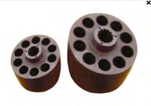
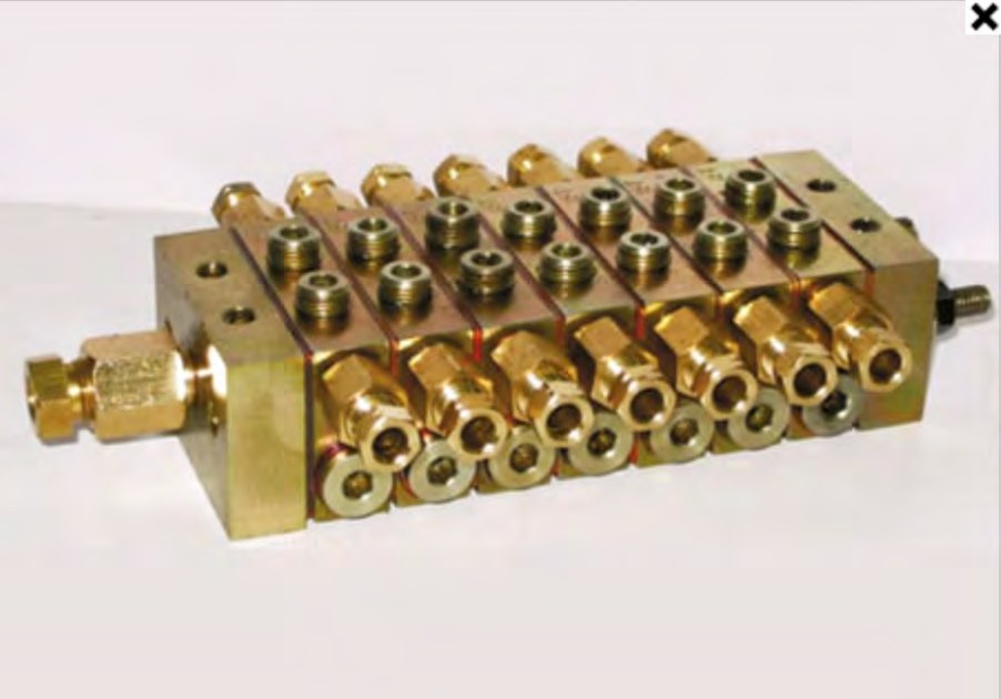
A hydraulic manifold is a solid block with intersecting drilled galleries carrying fluid at pressures from 210 to 420 bar. Any interconnected porosity between two galleries, or from a gallery to the outside face, is a leak path — and it is only discovered after the block has been fully machined.
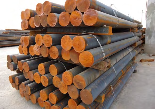
That single failure mode is why hydraulic component manufacturers move to continuous cast iron bar. The process eliminates the defects that create leak paths rather than trying to seal them afterwards.
This article covers the mechanism, the grade choice, and the design and machining practices that go with it.
Where porosity comes from — and why bar does not have it
In a sand mould, the last metal to solidify in a heavy section shrinks with no liquid behind it to feed the contraction. The result is microshrinkage: a network of fine cavities in exactly the region a cross-bore will later pass through. Add sand inclusions washed in from the mould and gas from the binder, and a machined face can open onto a leak path invisible before test.
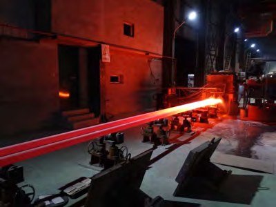
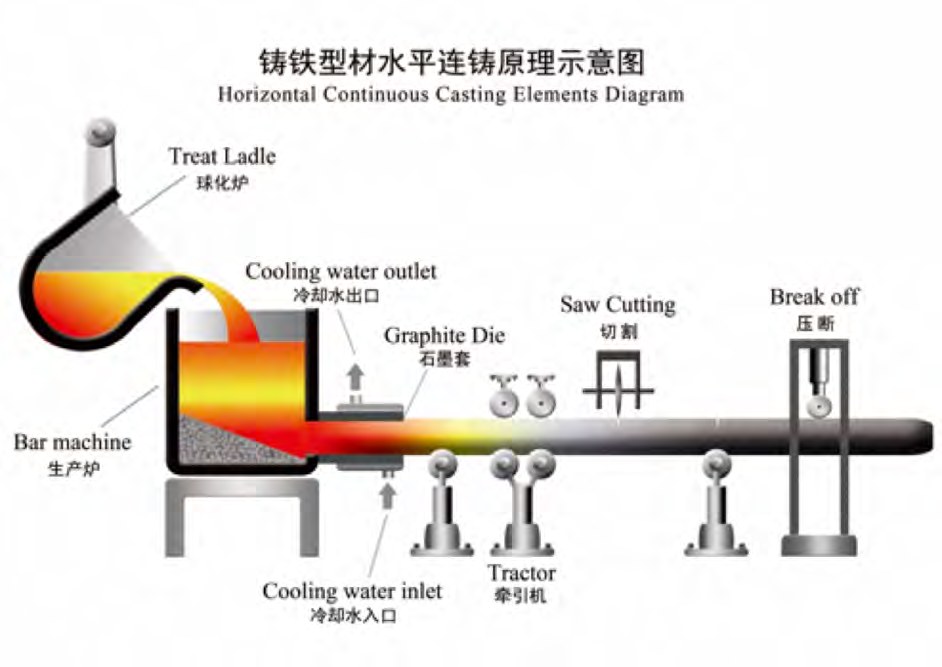
Continuous casting solidifies the bar progressively against a water-cooled graphite die while the holding furnace maintains a constant head of liquid metal behind the front. Contraction is fed continuously, so the cavity mechanism never operates. No sand touches the metal, so there are no inclusions to wash in.
Manifolds machined from continuous cast bar routinely pass hydrostatic and helium leak testing without resin impregnation — removing an entire outsourced process step, its lead time and its cost.
Grade selection for hydraulic parts
- QT500-7 / GGG50 — the default for manifolds, valve bodies and motor housings: 500–600 MPa tensile, ≥12% elongation, 180–210 HB, pressure tight and easy to machine.
- QT600-3 / GGG60 — where bolt loads, port stress or burst margin demand higher strength (≥560 MPa) and some elongation can be traded away.
- QT450-10 / GGG45 — where impact and elongation matter more than peak strength, for example mobile equipment exposed to shock loading.
- HT250 / GG25 — for low-pressure bodies, covers and pump housings where damping and cost dominate.
Machining and design practice
- Keep a minimum wall of roughly 4–5 mm between intersecting galleries; bar soundness removes the porosity risk, but wall stress still governs.
- Deburr cross-bore intersections — burrs, not the material, are the usual contamination source in a new circuit.
- Uniform 180–210 HB means gun-drilling and deep-hole boring hold straightness predictably across a batch.
- Machine sealing faces after gallery drilling so any drilling distortion is removed at final finishing.
- Order bar with the standard machining allowance from the tolerance table so all finished surfaces are cut from fully sound metal.
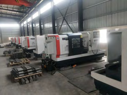
- Leak paths in hydraulic bodies come from shrinkage porosity and sand inclusions — both absent in continuous cast bar.
- Continuous liquid feed behind the solidification front is the mechanism that removes microshrinkage.
- Parts machined from bar typically pass pressure test without resin impregnation.
- QT500-7 is the default hydraulic grade; QT600-3 for higher stress, HT250 for low-pressure bodies.
- Uniform hardness supports predictable gun-drilling and deep-bore straightness.