Process Comparison

Continuous-Cast Iron Bar vs. Sand-Cast Blanks

Two routes to an iron component: semi-finished bar stock cut to length, or a shaped blank cast in sand. Where each route fits.

Quick Answer

Continuous-cast iron bar vs. Sand-cast blanks

Continuous-cast iron bar is semi-finished stock in round, square, rectangular or hollow section, produced by drawing iron continuously through a water-cooled graphite die and then machined into the final part. A sand-cast blank is poured into an expendable sand mould that already approximates the component shape. Bar suits parts that are close to a simple prismatic or rotational envelope, or where machining is extensive and a dense, consistent structure matters. Sand casting suits complex geometry, hollow or asymmetric shapes and larger sections, where near-net form saves a great deal of cutting. Neither is universally better — the deciding factors are geometry, section size, machining allowance and production volume.

Both routes deliver grey or ductile iron components, and both are covered by the same material standards — for example EN 1561 and ASTM A48 for grey iron, and EN 1563 and ASTM A536 for ductile iron. What differs is how the metal solidifies and how much of the final geometry comes from the mould rather than the cutting tool.

That difference in solidification is the heart of the comparison. It influences structural uniformity, the amount of stock a machinist has to remove, tooling wear, and whether features such as cored passages or thin ribs can be produced at all.

Reference Standards
  • EN 1561 / ASTM A48 — grey cast iron
  • EN 1563 / ASTM A536 — ductile (spheroidal graphite) iron
  • ISO 945 — graphite structure classification
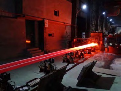
Continuous casting line producing solid cast iron bar stock
Detailed Comparison

Understanding the difference

COMP. 01 // ANALYSIS
SEC. 01

Understanding The Two Processes

In continuous casting, molten iron is fed from a holding furnace into a water-cooled graphite die. Solidification progresses inward from the die wall as the strand is withdrawn at a controlled rate, producing a long, straight length of one constant cross-section. Rapid, directional cooling against graphite generally gives a fine, uniform graphite and matrix structure with low porosity, which is why the material is supplied as machining stock.

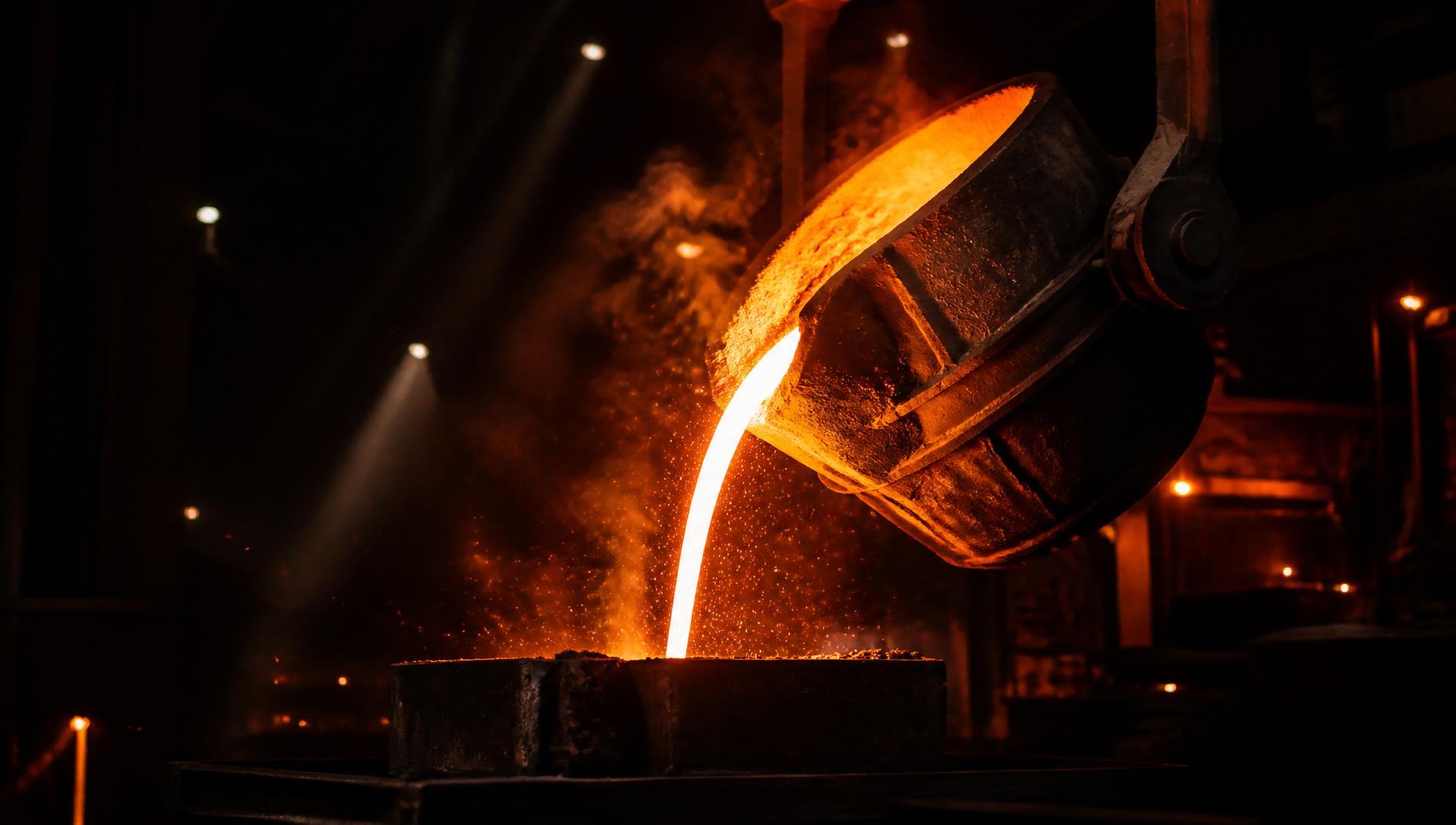
Sand casting forms an expendable mould from bonded sand around a pattern, with cores added for internal passages. Molten iron fills the cavity and solidifies at a rate set by section thickness and mould conductivity. Because the mould can reproduce almost any shape, the blank arrives already close to the finished component.

  • Continuous casting: one constant section, continuous length, chilled solidification against a graphite die.
  • Sand casting: shaped cavity per part, cores for internal features, solidification rate driven by section thickness.
  • Both routes can produce grey and ductile iron grades defined in EN and ASTM standards.
SEC. 02

Key Differences That Affect Design

The most practical difference is geometric freedom. Bar stock offers a fixed cross-section, so features must be produced by turning, milling, drilling or boring. Sand casting produces the shape directly, including flanges, bosses, webs and cast passages that would be uneconomic to machine from solid.

The second difference is structural consistency along the part. Continuous-cast bar has a section that solidified under essentially the same conditions along its whole length, so a machinist encounters comparable material from one end to the other and from one bar to the next. In a sand casting, thick and thin regions cool at different rates, so hardness and microstructure can vary between sections of the same part — a known and normal characteristic that designers manage through section design and feeding.

  • Geometry: sand casting wins on complexity; bar wins on simple prismatic and rotational shapes.
  • Consistency: bar gives repeatable material condition along its length; castings vary with section thickness.
  • Surface condition: bar has no mould skin or sand adhesion; castings carry a cast skin that must be broken through.
  • Lead time for a new part: bar needs no pattern; sand casting needs pattern and core tooling first.
SEC. 03

Manufacturing And Production Differences

Sand casting requires pattern equipment, and often core boxes, before the first part can be made. That tooling cost is amortised over the production run, which is why the route is normally chosen for repeat volume or for parts too complex to cut from solid.

Continuous-cast bar is a stock material. A component can be programmed and machined as soon as the correct section is available, which is why the route dominates prototypes, spares, low and medium volumes, and families of similar parts made from a common section.

Material utilisation runs the other way. Machining a part from bar converts the removed volume into chips, so a component with a large enclosed volume or a deep internal cavity is wasteful to cut from solid and much better cast to near-net shape.

SEC. 04

Machinability And Manufacturing Considerations

Grey iron machines freely in both routes because graphite flakes interrupt the chip and act as a lubricant. The practical difference is what the tool meets first. A sand casting presents a cast skin that can contain embedded moulding sand and localised hard spots at chilled edges, so first cuts are usually taken conservatively.

Continuous-cast bar has no mould skin and no sand, and its low porosity means fewer interruptions when a cut opens up a bore or a sealing face. Where the finished part must be pressure-tight or must present a continuous sealing surface, that absence of subsurface porosity is often the deciding argument.

  • Cast skin and possible sand inclusions make first cuts on sand castings harder on tooling.
  • Uniform, low-porosity bar stock supports predictable finishing and sealing surfaces.
  • Both grey iron variants require dry or minimum-lubrication practice and dust control for graphite.
SEC. 05

Material And Performance Considerations

Material class matters more than route. Grey iron offers excellent damping, thermal conductivity and compressive strength, with limited ductility. Ductile iron, where the graphite is present as nodules, offers substantially higher tensile strength and elongation and is chosen where impact or fatigue loading is expected.

Both routes can supply either family, and the specification should be written to the relevant material standard rather than to the casting method. Where a design is fatigue-critical or pressure-retaining, define the required grade, the test method and the acceptance criteria explicitly, and agree where test material is taken from.

Comparison Table

Factor-by-factor overview

COMP. 02 // TABLE
FactorContinuous-cast iron barSand-cast blanks
Manufacturing processContinuous withdrawal through a water-cooled graphite diePouring into an expendable bonded-sand mould
Geometry producedOne constant cross-section, cut to lengthNear-net component shape, including cored features
Tooling requiredNone — stock materialPattern and, where needed, core boxes
Structural uniformityConsistent along the length of the sectionVaries with local section thickness
Surface as suppliedMachining stock, no mould skinCast skin, cleaned and fettled
Machining allowanceWhole shape cut from the sectionLimited allowance on machined faces only
Material utilisationLower for hollow or enclosed shapesHigher — near-net form
Best-fit volumePrototypes to medium volume, spares, part familiesRepeat and higher-volume production
Typical useBushings, sleeves, guides, hydraulic bodies, wear platesHousings, manifolds, brackets, complex casings
Typical Applications

Where each option is normally used

COMP. 03 // APPLICATIONS

Continuous-cast iron bar

  • Bushings, bearing sleeves and wear rings
  • Hydraulic and pneumatic bodies and glands
  • Machine guides, wear strips and slide plates
  • Pump and compressor components
  • Spare parts and short-run replacements

Sand-cast blanks

  • Gearbox and pump housings
  • Manifolds with cast internal passages
  • Large brackets and structural casings
  • Heavy machine bases and frames
  • High-volume shaped components
Advantages & Limitations

Honest trade-offs on both sides

COMP. 04 // TRADE-OFFS

Continuous-cast iron bar

Advantages
  • No pattern cost and no tooling lead time
  • Uniform, dense structure with low porosity
  • Predictable machining and good surface finish
  • Fast route to prototypes, spares and part families
  • One section can serve many different parts
Limitations
  • Limited to available constant cross-sections
  • Wasteful for large enclosed volumes
  • All features must be machined
  • Section size range is bounded by the casting line

Sand-cast blanks

Advantages
  • Almost unrestricted geometry, including cored passages
  • Efficient material use on hollow and complex parts
  • Very large sections and weights are practical
  • Less material removed per finished part
  • Cost-effective once tooling is amortised
Limitations
  • Pattern and core tooling cost and lead time
  • Properties vary between thick and thin sections
  • Cast skin and possible sand inclusions affect first cuts
  • Design changes may require tooling rework
How To Choose

Material-selection considerations

COMP. 05 // SELECTION
  • 01Is the component close to a simple round, square, rectangular or hollow envelope? If yes, bar stock is usually the shorter route.
  • 02Does it contain cored passages, ribs, flanges or an enclosed cavity? If yes, sand casting will normally win on material and cycle time.
  • 03How many parts, and how soon? One-offs, spares and pilot runs favour bar; sustained repeat volume justifies pattern tooling.
  • 04How critical is the machined surface? Sealing faces, bores and pressure-retaining walls benefit from dense, low-porosity bar stock.
  • 05What section size is required? Very heavy sections and large footprints are the natural territory of sand casting.

Practical Conclusion

Treat the two routes as complementary rather than competing. Continuous-cast iron bar is the efficient answer when the part is geometrically simple, when tooling cannot be justified, or when a uniform low-porosity structure protects a critical machined surface. Sand casting is the efficient answer when geometry carries the value and volume justifies the pattern. Many machine builds use both — cast housings holding machined bar-stock bushings, guides and hydraulic bodies.

Discuss Your Component
FAQ

Frequently asked questions

COMP. 06 // FAQ

Start a project

Ready to work with Force Machining?

Send drawings, specs or a rough idea — our engineers get back within one business day.