
Process Comparison

Continuous Cast vs. Centrifugal Cast

Both produce semi-finished stock. One draws a constant section continuously; the other spins metal into a rotating mould.

Quick Answer

Continuous casting vs. Centrifugal casting

Continuous casting draws metal continuously through a water-cooled die to produce an unlimited length of one constant cross-section — round, square, rectangular or hollow — with a fine, uniform structure. Centrifugal casting pours metal into a rotating mould, where centrifugal force presses it against the mould wall; it excels at cylindrical and tubular shapes, especially large-diameter sleeves and liners, and tends to drive lower-density inclusions toward the bore, which is then machined away. Continuous casting suits high-volume standard sections and long straight stock; centrifugal casting suits large-diameter rings, sleeves and tubes and bi-metallic constructions.

Both processes deliver semi-finished stock intended for machining, and both are widely used for cast iron and for copper and nickel alloys. The difference is in how solidification is controlled: by directional chilling against a die, or by centrifugal pressure inside a spinning mould.

For a buyer, the practical consequences are the range of available sections, achievable wall thickness, machining allowance, and how much stock has to be removed from the bore.

Reference Standards
  • EN 1561 / ASTM A48 — grey cast iron
  • EN 1563 / ASTM A536 — ductile iron
  • ISO 945 — graphite classification
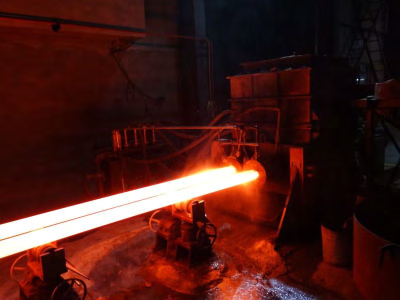
Glowing cast iron strand emerging from a continuous casting die
Detailed Comparison

Understanding the difference

COMP. 01 // ANALYSIS
SEC. 01

How Each Process Works

In continuous casting, molten metal enters a water-cooled graphite die and solidifies from the die wall inward while the strand is withdrawn at a controlled rate. Because conditions along the strand are constant, structure and dimensions are consistent along the whole length, and lengths are limited only by handling and cutting.

In centrifugal casting, a mould rotates about its axis — horizontally for long tubes, vertically for rings and shorter cylinders — while metal is poured in. Centrifugal force holds the metal against the mould wall and produces a sound outer surface, while lighter oxides and inclusions tend to collect at the inner diameter, where they are removed by boring.

  • Continuous casting: constant cross-section, continuous strand, directional chilling.
  • Centrifugal casting: rotating mould, dense outer wall, inclusions concentrated at the bore.
  • Both are semi-finished routes intended for subsequent machining.
SEC. 02

Section And Size Capability

Continuous casting is strongest for solid bar and modest hollow sections in the sizes carried as standard stock, and for non-round profiles such as square and rectangular sections. Its economics improve with long runs of one section.

Centrifugal casting is strongest where diameter grows. Large sleeves, cylinder liners, rings and long tubes are natural centrifugal parts, and the process can also produce bi-metallic components by pouring a second alloy against a first, which continuous casting cannot do.

SEC. 03

Structure And Machining Allowance

Continuous-cast sections have a uniform, fine structure and are supplied as machining stock with a predictable allowance, so a machinist can plan cuts confidently.

Centrifugally cast tubes carry more allowance on the bore because the inner region is expected to be removed. Once bored, the remaining wall is typically dense and sound, which is exactly what a wear sleeve or liner requires.

  • Continuous cast: consistent structure along length, modest and predictable allowance.
  • Centrifugal cast: dense outer wall, generous bore allowance by design.
  • Both require the material grade and test regime to be stated in the order.
SEC. 04

Choosing Between The Two

If the part is a shaft, bushing, guide, gland or prismatic body within standard section sizes, continuous-cast stock is normally the shorter and cheaper route. If the part is a large-diameter sleeve, liner, ring or long tube — or needs two different alloys in one wall — centrifugal casting is the process built for it.

Comparison Table

Factor-by-factor overview

COMP. 02 // TABLE
FactorContinuous castingCentrifugal casting
Solidification controlDirectional chilling against a water-cooled dieCentrifugal pressure inside a rotating mould
Shapes producedRound, square, rectangular, modest hollow sectionsCylinders, tubes, rings, sleeves
Length capabilityContinuous strand, cut to lengthLimited by mould length
Large diametersBounded by the casting lineA core strength of the process
Inclusion behaviourLow porosity through controlled chillingInclusions driven to the bore and machined out
Machining allowanceModest and predictableGenerous on the bore by design
Bi-metallic capabilityNot applicablePossible with sequential pouring
Best-fit partsBushings, guides, glands, prismatic bodiesCylinder liners, large sleeves, rings, tubes
Typical Applications

Where each option is normally used

COMP. 03 // APPLICATIONS

Continuous casting

  • Bushings and bearing sleeves
  • Hydraulic bodies and glands
  • Machine guides and wear plates
  • Gear and pulley blanks
  • General machining stock

Centrifugal casting

  • Cylinder liners
  • Large-diameter wear sleeves
  • Rings and flange blanks
  • Pipe and tube stock
  • Bi-metallic sleeves and rolls
Advantages & Limitations

Honest trade-offs on both sides

COMP. 04 // TRADE-OFFS

Continuous casting

Advantages
  • Uniform structure along the whole length
  • Non-round profiles available
  • No mould per part; long continuous lengths
  • Predictable machining allowance
  • Efficient for repeated standard sections
Limitations
  • Limited to available cross-sections
  • Large-diameter hollow parts are impractical
  • All shaping is done by machining

Centrifugal casting

Advantages
  • Dense, sound outer wall
  • Excellent for large diameters and long tubes
  • Inclusions concentrate where they are machined away
  • Bi-metallic constructions possible
  • Efficient use of metal for tubular parts
Limitations
  • Essentially restricted to axisymmetric shapes
  • Bore requires generous machining allowance
  • Mould length limits part length
  • Higher setup effort per size
How To Choose

Material-selection considerations

COMP. 05 // SELECTION
  • 01Is the finished part axisymmetric with a significant bore? Centrifugal stock reduces material removal.
  • 02Is the part a solid or lightly bored prismatic component? Continuous-cast bar is normally the simplest route.
  • 03How large is the diameter? Above the range carried as bar stock, centrifugal casting becomes the practical option.
  • 04Do you need two alloys in one wall, such as a wear-resistant inner layer? Only centrifugal casting supports that.
  • 05Confirm the required grade and inspection regime in the order for either route.

Practical Conclusion

These are complementary semi-finished routes, not competitors. Continuous casting owns standard bar and profile stock for machined components; centrifugal casting owns large cylindrical and tubular stock. Matching the part's geometry to the process that naturally produces it minimises both material waste and machining time.

Discuss Your Component
FAQ

Frequently asked questions

COMP. 06 // FAQ

Start a project

Ready to work with Force Machining?

Send drawings, specs or a rough idea — our engineers get back within one business day.